Tutorial: Connecting Networks to CloudConnexa Using Connectors
This tutorial explains why certain configurations, such as NAT, IP forwarding, and adding static routes, are needed. It also informs on the settings for virtual machines in IaaS providers to act as software routers.
This tutorial explains why certain configurations, such as NAT, IP forwarding, and adding static routes, are needed. It also informs on the settings for virtual machines in IaaS providers to act as software routers.
After downloading and installing the OpenVPN Connector software, additional steps might be needed to ensure proper traffic routing between your private networks and CloudConnexa. In this document, we examine traffic flows in depth to help you understand why certain actions must be taken and provide instructions and references for configuring the required functionality on the instance running the Connector.
Note
The Connector install scripts of virtual machines running Linux already contain the commands to enable IP forwarding (routing) and NAT. Refer to CloudConnexa Connectors
Traffic flow for remote access to private IP Services
In this section, the traffic flow between a remote User connected to CloudConnexa and the HR application on the HQ Network is examined.
As shown in the figure, HQ Network comprises the 10.0.0.0/18 subnet and a computer running Ubuntu acts as the Connector on IP address 10.0.0.10. The HR application server is at 10.0.0.20. The HQ Network is connected to the Internet by a router that performs Network Address Translation (NAT) to provide the computers on the internal private Network with access to the Internet.
From this flow, it will be apparent why the instance running the Connector needs to act as a software router and use NAT.

The Admin adds a Network using the CloudConnexa Administration portal. The Network is named ‘HQ Network,’ and
10.0.0.0/18is added as its subnet.CloudConnexa in the background assigns
100.96.0.100as the tunnel IP address for the Connector created for HQ Network and configures its routing table to forward all traffic destined to the HQ Network’s subnets (10.0.0.0/18) to its Connector (100.96.0.100).Admin downloads and installs the Connector software and connects with the CloudConnexa Profile to establish an OpenVPN tunnel to the preconfigured CloudConnexa Region.
During tunnel establishment, CloudConnexa pushes down a route to the WPC Subnet range (
100.96.0.0/11).Once the tunnel is established, the tunnel is represented by a virtual interface that receives packets from the WPC and will be used to send packets destined to
100.96.0.0/11.Admin configures a User named Bob in a User Group with its Internet Access set to (Split-Tunnel ON).
Bob receives the invitation email, downloads the Connect client, and imports the Profile after selecting the closest Region.
On connection, because Split-Tunnel is ON the virtual interface receives routes for both the CloudConnexa WPC IP subnet range as well as the subnet range of HQ Network.
Bob tries to access the HR application. Since the HR application is in the HQ Network, the packet is routed via the WPC interface.
When CloudConnexa receives the packet, it checks its routing table and directs it to the Connector in HQ Network because the destination IP address is in the subnet configured for HQ Network.
When the Connector instance receives a packet destined for
10.0.0.20, it drops it because the computer only expects to receive packets destined for it at10.0.0.10or100.96.0.100For the Connector instance to accept the packet destined at
10.0.0.20received from its tunnel interface and send it to the HQ Network LAN, the Connector needs to be configured to act as a router and forward IP packets using the right interface.Now that routing is enabled, the Connector instance forwards the packet received on the LAN interface to reach the HR Application server.
The Application server responds to the packet, and because it does not know how to route to send it destined for an IP address in
100.96.0.0/11, it sends it to its default route, the router.When the router receives the packet, it drops it because there are no entries on how to route it, and the destination IP address is not routable on the Internet.
To resolve this issue, a static route can be added to the router, instructing it to forward all traffic destined to
100.96.0.0/11to the Connector instance. See the section on Add static routes.With the static route in place, the packet is forwarded to the Connector instance which, already configured as a router, can route it via the WPC to its final destination (steps 21-22).
NAT can be enabled on the Connector instance as an alternative to configuring the router with a static route. When NAT is turned ON, the Connector instance will substitute its IP address for the original source IP address and, upon receiving the response, switch the destination to the original source IP.
The packet now gets forwarded by the Connector instance and undergoes NAT so that when the packet is received by the Application Server , it need not forward the response to the router but send it right back to the Connector Instance.
When it receives the response, the Connector instance translates the destination and can forward it to the tunnel interface.
The response reaches the Connector instance using Option 1 (static route) or Option 2 (NAT) and is sent to CloudConnexa.
CloudConnexa forwards the packet to Bob.
Option 1 or Option 2 — which is better? The static route Option 1 is better if you anticipate sending unsolicited traffic to remote clients from the Network. For example, if you want to ping Bob’s WPC IP address from the Application Server. NAT Option 2 is fine as long as all traffic sessions are always initiated by the remote client.
Note
The Connector install scripts of virtual machines running Linux already contain the commands to enable IP forwarding (routing) and NAT. Refer to CloudConnexa Connectors
Traffic flow for use of a private network as an internet gateway
This traffic flow shows how internet traffic exiting CloudConnexa and egressing from HQ Network is handled.
As shown in the figure, HQ Network comprises the 10.0.0.0/18 subnet, and a computer running Ubuntu is acting as the Connector on IP address 10.0.0.10. The HQ Network is connected to the Internet by a router that performs Network Address Translation (NAT) to provide the computers on the internal private Network with access to the Internet. The service on the Internet that Bob is accessing is at the IP address 107.3.152.27.
From this flow, it will be apparent why the instance running the Connector needs to act as a software router and use NAT.
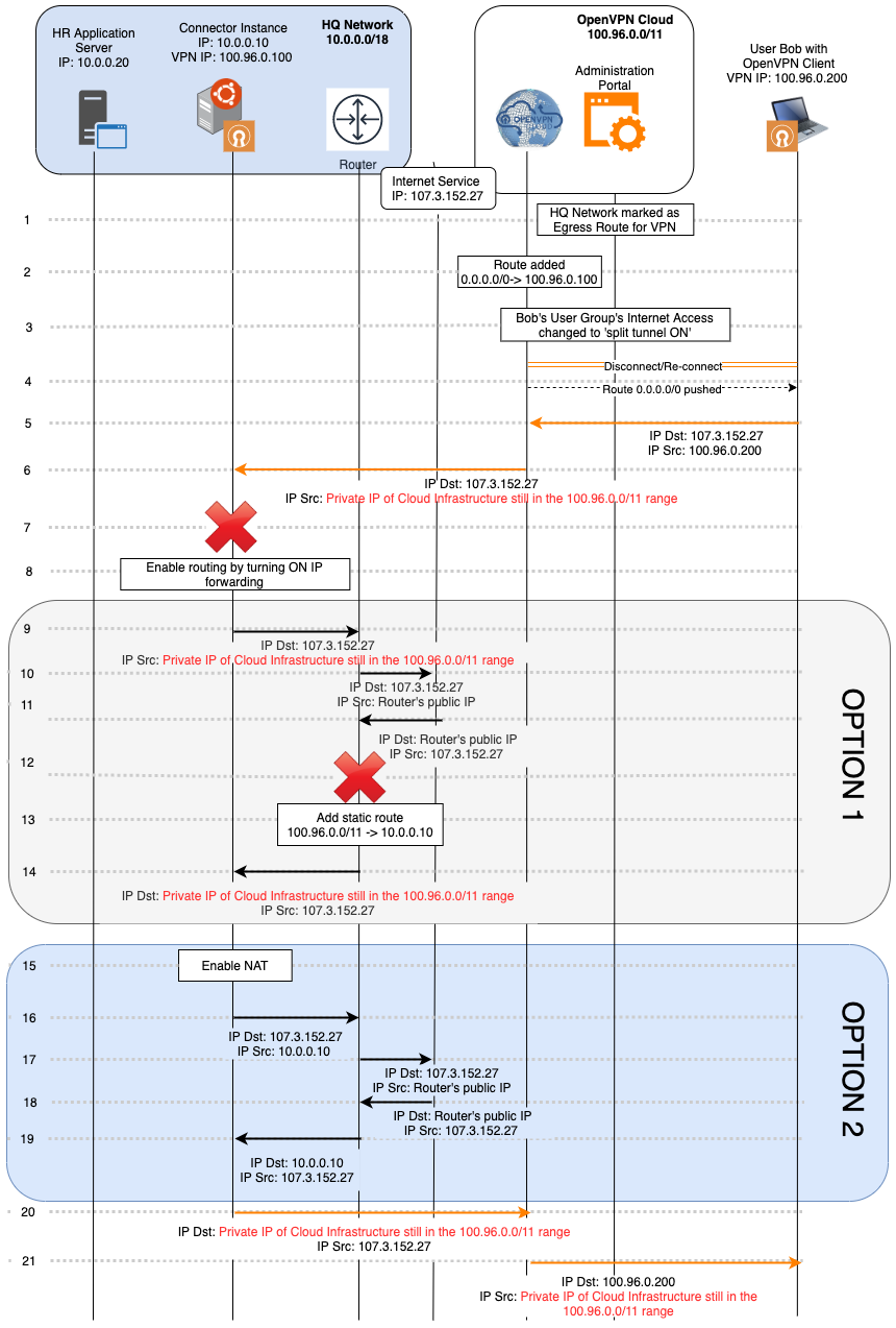
The Admin marks 'HQ Network' as an Internet Gateway for the WPC using the CloudConnexa Administration portal.
In the background, CloudConnexa adds the IP address of the HQ Network Connector as the default route for the WPC.
The Admin sets the internet access of the User Group to which Bob belongs to Split-Tunnel OFF.
Bob’s OpenVPN tunnel is reset and CloudConnexa is the default route destination.
Bob tries to access an Internet application (server IP address of
107.3.152.27). As CloudConnexa is the default route, the packet is routed via the tunnel interface.When CloudConnexa receives the packet, it checks its routing table and directs the packet to the Connector in HQ Network because it has been set as the egress route for the WPC.
When the Connector instance receives a packet destined for 107.3.152.27 , it drops it because the computer only expects to receive packets destined for it at either
10.0.0.10or100.96.0.100.For the Connector instance to accept the packet destined at
107.3.152.27received from its tunnel interface and send it to the HQ Network LAN, it must be configured to act as a router and forward IP packets using the right interface.Now that routing is enabled, the Connector instance forwards the packet received on the LAN interface to reach the Network’s router.
The router performs NAT and forwards the packet to the server on the Internet.
When the router receives the response, it performs the NAT translation to get the destination address as an IP address in
100.96.0.0/11.The router drops the response because there are no entries to route this packet, and the destination IP address is not routable on the internet.
To resolve this issue, a static route can be added to the router, instructing it to forward all traffic destined to
100.96.0.0/11to the Connector instance. See the section on Add static routes.With the static route in place, the packet is forwarded to the Connector instance, which, already configured as a router, can route it via the WPC to its final destination (steps 20-21).
NAT can be enabled on the Connector instance as an alternative to configuring the router with a static route. When NAT is turned ON, the Connector instance will substitute its IP address for the original source IP address and, upon receiving the response, switch the destination to the original source IP.
The packet now gets forwarded by the Connector instance and undergoes NAT so that when it is received by the router, the source IP address is
10.0.0.10and not the IP address in100.96.0.0/11.The router performs NAT and forwards the packet to the server on the Internet.
When the router receives the response, it performs the NAT translation to get the destination address as
10.0.0.10(because the Connector instance had performed NAT on step 16) and forwards the response to the Connector instance.On receiving the response, the Connector instance translates the destination back to the IP address in
100.96.0.0/11and can forward the response on the tunnel interface.The response reaches the Connector instance using Option 1 (static route) or Option 2 (NAT) and is sent to CloudConnexa.
CloudConnexa forwards the packet to Bob.
Option 1 or Option 2 which option is better? The static route Option 1 is better if you anticipate sending unsolicited traffic to remote clients from the Network and if the router will perform NAT for source IP addresses that do not belong to the HQ Network. NAT Option 2 is fine as long as all traffic sessions are always initiated by the remote client.
Note
The Connector install scripts of virtual machines running Linux already contain the commands to enable IP forwarding (routing) and NAT. Refer to CloudConnexa Connectors
Traffic flow for site-to-site networking
The flow below shows the traffic flows between two sites connected to CloudConnexa: HQ Network and Branch Network.
This traffic flow will explain why adding static routes to the network routers on both sites is mandatory. As new sites are added to CloudConnexa, it is mandatory to add to the existing static routes on each site a route to the new Network’s subnets. See the section on Add static routes
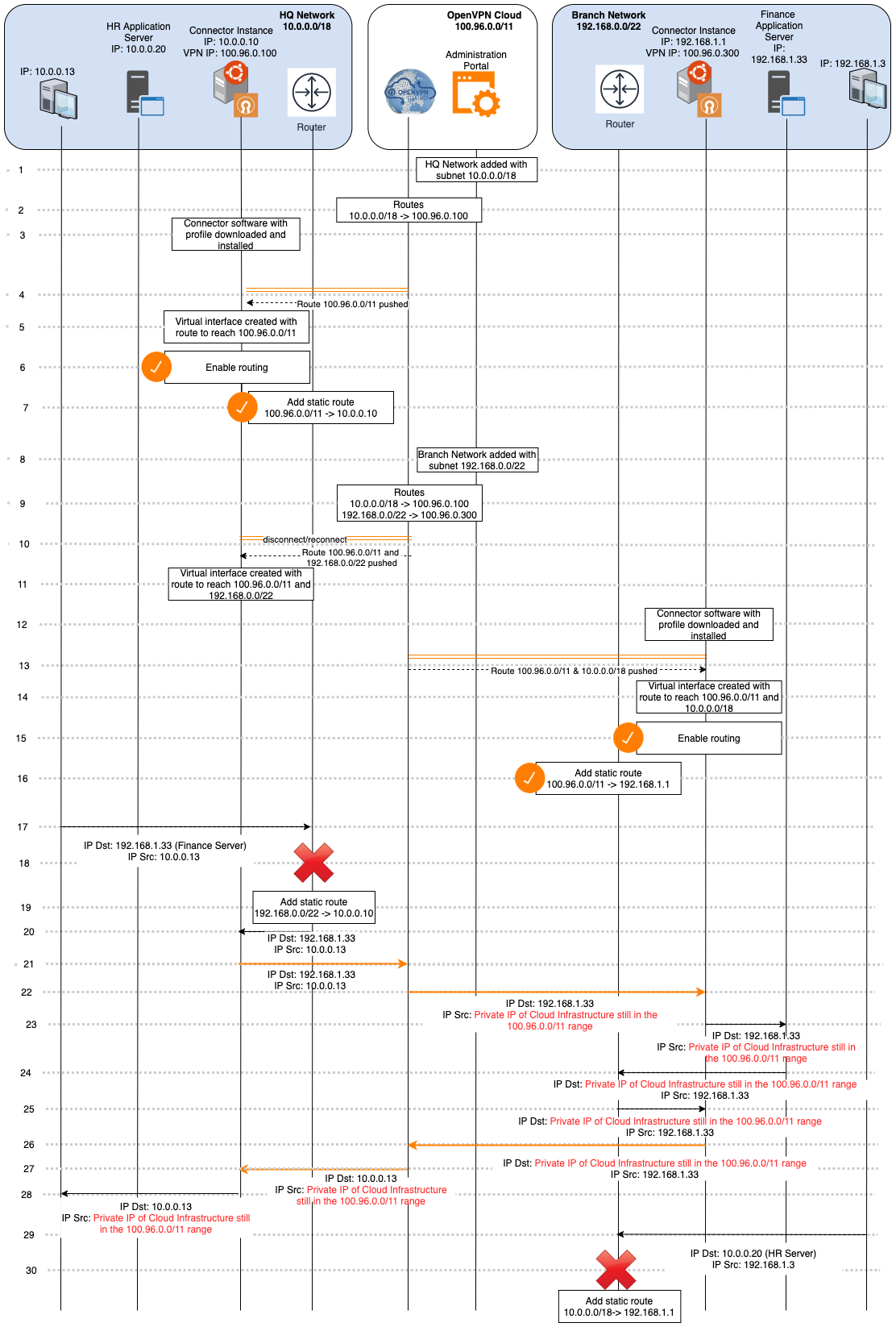
The Administrator adds a Network using the CloudConnexa Administration portal. The network is named ‘HQ Network,’ and
10.0.0.0/18is added as its subnet.CloudConnexa in the background assigns
100.96.0.100as the tunnel IP address for the Connector created for HQ Network and configures its routing table to forward all traffic destined to the HQ Network’s subnets (10.0.0.0/18) to its Connector (100.96.0.100).Admin downloads and installs the Connector software and connects with the CloudConnexa Profile to establish an OpenVPN tunnel to the preconfigured CloudConnexa Region.
During the establishment of an OpenVPN tunnel connection, CloudConnexa pushes down a route to the WPC Subnet range (
100.96.0.0/11).Once the connection is established, the tunnel is represented by a virtual interface that receives packets from the WPC and will be used to send packets destined to
100.96.0.0/11.In order for the Connector instance to accept packets received from its tunnel interface and send them to the HQ Network LAN, it needs to be configured to act as a router and forward IP packets using the right interface.
A static route is added to the router, instructing it to forward all traffic destined for CloudConnexa (
100.96.0.0/11) to the Connector instance. See the section on Add static routes.The Administrator adds a Network using the CloudConnexa Administration portal. The Network is named ‘Branch Network,’ and
192.168.0.0/22is added as its subnet.CloudConnexa, in the background, assigns
100.96.0.300as the tunnel IP address for the Connector created for the Branch Network and configures its routing table to forward all traffic destined to the Branch Network’s subnets(192.168.0.0/22)to its Connector(100.96.0.300).WPC Connection to HQ Network’s Connector is quickly reset to push the new route of
192.168.0.0/22.Now, the tunnel virtual interface will reach both CloudConnexa and Branch Network.
Admin downloads and installs the Connector software and connects with the CloudConnexa Profile to establish an OpenVPN tunnel to the preconfigured CloudConnexa Region.
During WPC connection establishment CloudConnexa pushes down a route to the WPC Subnet range (
100.96.0.0/11) and the HQ Network subnet range10.0.0.0/18.Once the connection is established, the OpenVPN tunnel is represented by a virtual interface that receives packets from it and will be used to send packets destined for
100.96.0.0/11and10.0.0.0/18.In order for the Connector instance to accept the packets received from its WPC interface and send them to the Branch Network LAN, the Connector needs to be configured to act as a router and forward IP packets using the right interface.
A static route is added to the router, instructing it to forward all traffic destined for CloudConnexa (100.96.0.0/11) to the Connector instance.
A computer on HQ Network now tries to reach the Finance Server on the Branch Network. It sends the packet to the Network’s router.
The router drops the packet because it has no route to reach the
192.168.0.0/22Network.A static route is added with the Connector instance as the destination for the Branch Network subnet.
Now, the packet is forwarded to the Connector instance from the router.
With routing already enabled, the Connector instance sends the packet to CloudConnexa using the WPC interface.
CloudConnexa forwards the packet to the Connector instance in Branch Network.
When the Connector instance receives the packet destined for the Finance Server, it forwards it to the LAN interface because it has already been set up as a router.
The Finance Server responds to the request but sends it to the Network’s router because the destination IP address of
10.0.0.0.13does not belong to its LAN.The router forwards the packet to the Connector because of the static route configured for
100.96.0.0/11.With routing already enabled, the Connector instance sends the packet to CloudConnexa using the tunnel interface.
CloudConnexa forwards the packet to the Connector instance in HQ Network.
When the Connector instance receives the packet destined for the computer on its LAN, it forwards it to the LAN interface because it has already been set up as a router.
Now, a computer on the Branch Network tries to access the HR server that is in the HQ Network by sending the request packet to the router.
As the router does not have a static route for the HQ Network IP address range, it must be added to send the traffic flow to the Connector.
Note
The Connector install scripts of virtual machines running Linux already contain the commands to enable IP forwarding (routing) and NAT. Refer to CloudConnexa Connectors
Add static routes
All routers provide the ability to add a static route. Please refer to your router documentation. For Virtual Cloud Networks, we have provided references below for some IaaS providers.
A static route needs to be added to the WPC IP address range of CloudConnexa. The default WPC IP address range is 100.96.0.0/11 for CloudConnexa. The static route added should have 100.96.0.0/11 as the destination IP address range and the private IP address of the Connector instance as the Target.
A static route needs to be added for the destination subnet ranges of your other Networks that are connected to CloudConnexa too.
The figure below shows the static routes added to a VPC route table. You can see that there are three routes pointing to eni-06e725657ba3a8f63 (the instance that is running the Connector software). 172.31.0.0/16 is the subnet of another Network that can be accessed via CloudConnexa.
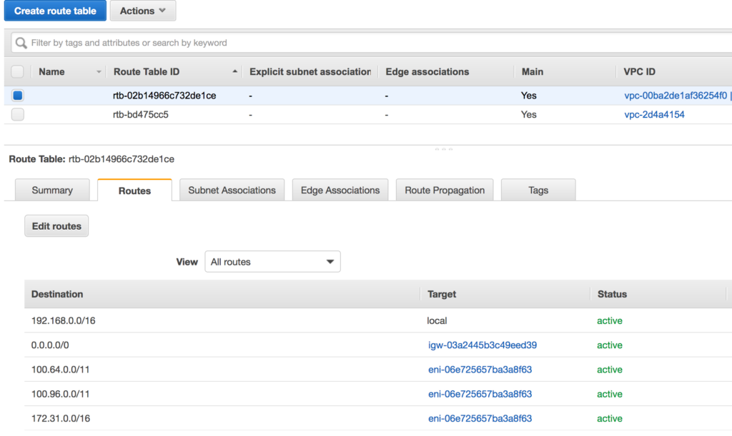
AWS: During the AWS Connector install using CloudFormation, there is a ManageRoutes option. Select True if you are doing a site-to-site setup and want to automatically push the subnets of the other sites to the VPC routing table.
Azure: Azure calls static routes as ‘User-defined’. See, https://docs.microsoft.com/en-us/azure/virtual-Network/virtual-Networks-udr-overview
GCP: https://cloud.google.com/vpc/docs/using-routes
Oracle Cloud: See, using Private IP as a route target https://docs.cloud.oracle.com/en-us/iaas/Content/Network/Tasks/managingroutetables.htm#Route
Source/Dest check considerations for IaaS
Virtual servers provided by IaaS providers use virtual Network interface cards (VNIC). Every VNIC performs the source/destination check on its Network traffic by default. The VNIC looks at the source and destination listed in the header of each Network packet. The packet is dropped if the VNIC is not the source or destination.
For the Connector to perform routing or NAT functionality on the instance on which it is installed, the Source/Dest check on the VNIC needs to be turned OFF.
Please refer to the documentation your IaaS provides to disable source/dest check. For your convenience documentation, references are provided below:
AWS: https://docs.aws.amazon.com/vpc/latest/userguide/VPC_NAT_Instance.html#EIP_Disable_SrcDestCheck
Oracle: https://docs.oracle.com/en-us/iaas/Content/Network/Tasks/managingVNICs.htm
Azure: IP forwarding must be enabled at the VNIC https://docs.microsoft.com/en-us/azure/virtual-Network/virtual-Network-network-interface#enable-or-disable-ip-forwarding
GCP: https://cloud.google.com/vpc/docs/using-routes#canipforward
Also, note that when running some Linux firewall packages, rpfilter is sometimes turned On
https://tldp.org/HOWTO/Adv-Routing-HOWTO/lartc.kernel.rpf.html. In addition to source/dest check, rp_filter in sysctl.conf should be turned Off
Security Considerations for IaaS
If you are using security groups to protect any instances that need their traffic routed through the Connector instance, you need to add the Connector instance's security group to their inbound rules. Learn more about AWS Security Groups here.